L3VPN was one of the recent challenges for me in routing and switching world as it introduces many new concepts that change conventional routing as we know it, but with a lot of reading, lab scenarios I became quite comfortable with L3VPN now. To be honest, even though it is really a complex topic, I think most of the books were not doing a good job explaining this. I had to read CCIE cert guide, BGP implementation and then MPLS fundamentals to finally be able to work some lab scenarios. Only then, I started to get the big picture of how L3VPN works. Now I am glad to share what I learnt so far in this post.
I will try to avoid the specific details that explain these concepts as you can review these in the above mentioned books. However, I will configure a complete network (with four different possible scenarios) from scratch which will make it easier to understand L3VPN, also I will explain as much as I can along with each step in the config to make sure that we’re all on the same page.
Design Objectives:
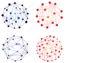
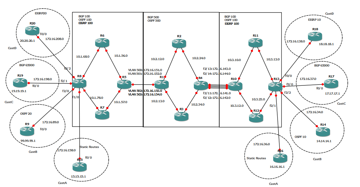
We have 4 customers, each has two remote sites. We have an ISP that has two NNIs (Network-to-Network Interfaces) connected to another ISP. This is to simulate a smaller ISP (AS500) that is being supported by a bigger ISP (AS200) where they own a larger infrastructure so they connect to the customer sites on both ends to provide IP connectivity to the smaller ISP. I have designed this for a reason which I will explain as we move forward.
For now, we need each customer to have full IP connectivity between both sites. However, no customer should be able to reach another customer’s site. We will change this later on.
Both ISP networks have OSPF instances advertising all links and Router IDs. MPLS is also enabled on all ISP 12 routers and their inter-links. Links between PEs (R8 and R13) and CEs have no MPLS configured on them. I will explain in depth the configuration of the links between R5/R1 and R4/R10.
I will skip the base config: IP addresses, the underlying routing protocol (EIGRP, OSPF or ISIS should work, I chose OSPF) on all ISP routers (remember to advertise all links and router IDs). RID is the router number in dotted decimal format. Please refer to the DIAGRAM.
Note: The method that I’m using in this example is called Back to Back VRFs. I will have another post where I’m going to slightly modify this design and use Carrier Supporting Carrier or CsC to achieve the same goal.
Now the fun begins.
1) Enabling MPLS on all ISP routers and their links EXCEPT for PE-CE and ISP to ISP (R5-to-R1 and R4-to-R10) links. Remember, ISPs don’t share their MPLS cloud, ie they don’t exchange LDP labels. Also, as mentioned above, MPLS will not be enabled on PEs’ interfaces with the CEs.
Below is a sample config to turn MPLS on R1. You will need to repeat this for all routers in each ISP.
R1
ip cef
mpls ip
mpls label protocol ldp
!
interface f0/0
mpls ip
!
interface f1/0
mpls ip
!
2) Configuring VRFs for each ISP and per customer: VRFs are only needed on PEs.
ISP (AS 500)
R1 and R4:
ip vrf CUSTA500
rd 500:100
route-target export 500:100
route-target import 500:100
!
ip vrf CUSTB500
rd 501:101
route-target export 501:101
route-target import 501:101
!
ip vrf CUSTC500
rd 502:102
route-target export 502:102
route-target import 502:102
!
ip vrf CUSTD500
rd 503:103
route-target export 503:103
route-target import 503:103
!
ISP (AS100)
R8 and R5:
ip vrf CUSTA100
rd 100:10
route-target export 100:10
route-target import 100:10
!
ip vrf CUSTB100
rd 200:20
route-target export 200:20
route-target import 200:20
!
ip vrf CUSTC100
rd 300:30
route-target export 300:30
route-target import 300:30
!
ip vrf CUSTD100
rd 400:40
route-target export 400:40
route-target import 400:40
!
ISP(AS100)
R10 and R 13:
ip vrf CUSTA111
rd 111:11
route-target export 111:11
route-target import 111:11
!
ip vrf CUSTB222
rd 222:22
route-target export 222:22
route-target import 222:22
!
ip vrf CUSTC222
rd 333:33
route-target export 333:33
route-target import 333:33
!
ip vrf CUSTD222
rd 444:44
route-target export 444:44
route-target import 444:44
!
I think there is a couple of points that are worth mentioning here. Notice that for the same ISP ASN 100 I am using different VRFs for each customer. In the real world, since this is the same ISP, the same VRF within the ISP cloud should be used for each customer. But since I am not directly connecting the two clouds, I used different VRFs. Also, I wanted to explain a few workarounds for the problem of having a repeated AS in the BGP AS path. The other reason is just to show that having different VRFs will not break the customer connectivity within different clouds. I hope this is less confusing now!
Now, we will configure the NNIs. I used two different ways of connecting two ISP backbones. One with dedicated physical interfaces and the other with subinterfaces. Obviously, when using physical interfaces, you will need a new dedicated port, and someone to physically connect a cable between the two ISP routers for each new customer. While when using subinterfaces, you just need to configure a new sub-interfaces for each new customer. Very convenient!
R5:
interface FastEthernet2/0
no ip address
speed 100
full-duplex
!
interface FastEthernet2/0.500
encapsulation dot1Q 500
ip vrf forwarding CUSTA100
ip address 172.16.151.2 255.255.255.0
!
interface FastEthernet2/0.501
encapsulation dot1Q 501
ip vrf forwarding CUSTB100
ip address 172.16.152.2 255.255.255.0
!
interface FastEthernet2/0.502
encapsulation dot1Q 502
ip vrf forwarding CUSTC100
ip address 172.16.153.2 255.255.255.0
!
interface FastEthernet2/0.503
encapsulation dot1Q 503
ip vrf forwarding CUSTD100
ip address 172.16.154.2 255.255.255.0
!
R1:
interface FastEthernet2/0
no ip address
speed 100
full-duplex
!
interface FastEthernet2/0.500
encapsulation dot1Q 500
ip vrf forwarding CUSTA500
ip address 172.16.151.1 255.255.255.0
!
interface FastEthernet2/0.501
encapsulation dot1Q 501
ip vrf forwarding CUSTB500
ip address 172.16.152.1 255.255.255.0
!
interface FastEthernet2/0.502
encapsulation dot1Q 502
ip vrf forwarding CUSTC500
ip address 172.16.153.1 255.255.255.0
!
interface FastEthernet2/0.503
encapsulation dot1Q 503
ip vrf forwarding CUSTD500
ip address 172.16.154.1 255.255.255.0
!
VLAN numbers don’t really matter as long as they are unique per customer, and obviously they have to match on both ends of the ISP NNIs.
R4:
interface FastEthernet2/11
no switchport
ip vrf forwarding CUSTA500
ip address 172.16.141.1 255.255.255.0
duplex full
speed 100
!
interface FastEthernet2/12
no switchport
ip vrf forwarding CUSTB500
ip address 172.16.142.1 255.255.255.0
duplex full
speed 100
!
interface FastEthernet2/13
no switchport
ip vrf forwarding CUSTC500
ip address 172.16.143.1 255.255.255.0
duplex full
speed 100
!
interface FastEthernet2/14
no switchport
ip vrf forwarding CUSTD500
ip address 172.16.144.1 255.255.255.0
duplex full
speed 100
!
R10:
interface FastEthernet2/11
no switchport
ip vrf forwarding CUSTA111
ip address 172.16.141.2 255.255.255.0
duplex full
speed 100
!
interface FastEthernet2/12
no switchport
ip vrf forwarding CUSTB222
ip address 172.16.142.2 255.255.255.0
duplex full
speed 100
!
interface FastEthernet2/13
no switchport
ip vrf forwarding CUSTC222
ip address 172.16.143.2 255.255.255.0
duplex full
speed 100
!
interface FastEthernet2/14
no switchport
ip vrf forwarding CUSTD222
ip address 172.16.144.2 255.255.255.0
duplex full
speed 100
!
3) configuring MP-BGP for each ISP cloud.
R8:
router bgp 100
no synchronization
bgp router-id 8.8.8.8
bgp log-neighbor-changes
neighbor 5.5.5.5 remote-as 100
neighbor 5.5.5.5 update-source Loopback8
no auto-summary
!
address-family vpnv4
neighbor 5.5.5.5 activate
neighbor 5.5.5.5 send-community both
exit-address-family
!
R5:
router bgp 100
bgp router-id 5.5.5.5
bgp log-neighbor-changes
neighbor 8.8.8.8 remote-as 100
neighbor 8.8.8.8 update-source Loopback5
!
address-family vpnv4
neighbor 8.8.8.8 activate
neighbor 8.8.8.8 send-community both
exit-address-family
!
R1:
router bgp 500
no synchronization
bgp router-id 1.1.1.1
neighbor 4.4.4.4 remote-as 500
neighbor 4.4.4.4 update-source Loopback1
no auto-summary
!
address-family vpnv4
neighbor 4.4.4.4 activate
neighbor 4.4.4.4 send-community both
exit-address-family
!
R4:
router bgp 500
no synchronization
bgp router-id 4.4.4.4
bgp log-neighbor-changes
neighbor 1.1.1.1 remote-as 500
neighbor 1.1.1.1 update-source Loopback4
no auto-summary
!
address-family vpnv4
neighbor 1.1.1.1 activate
neighbor 1.1.1.1 send-community both
exit-address-family
!
R10:
router bgp 100
no synchronization
bgp router-id 10.10.10.10
bgp log-neighbor-changes
neighbor 13.13.13.13 remote-as 100
neighbor 13.13.13.13 update-source Loopback10
no auto-summary
!
address-family vpnv4
neighbor 13.13.13.13 activate
neighbor 13.13.13.13 send-community both
exit-address-family
!
R13:
router bgp 100
no synchronization
bgp log-neighbor-changes
neighbor 10.10.10.10 remote-as 100
neighbor 10.10.10.10 update-source Loopback13
no auto-summary
!
address-family vpnv4
neighbor 10.10.10.10 activate
neighbor 10.10.10.10 send-community both
exit-address-family
!
Few points to mention here:
1) There is no need to configure BGP on P routers within the ISP cloud.
2) To configure a MP-BGP between PEs, as shown above, you need to use the (neighbor ip-address remote-as asn) command under the BGP process as usual. However, you will need to use (neighbor ip-address activate) command under (address-family vpn4) process.
I’ll use few different show commands to confirm BGP connectivity. Notice the
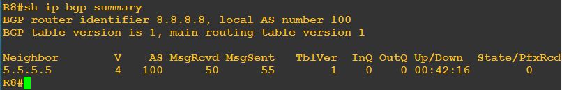
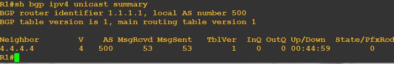
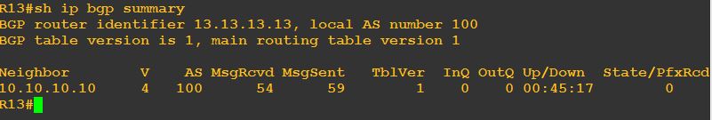
Adding new customer will need no further update on the above config. You will need to configure it only once. However, obviously, we are not done yet. We still have to configure the CE-PEs and PE-PEs for each newly added customer.
There are three ways for the ISP to connect to a customer site. By using static routes, IGPs or BGP. In my design, I have used all four (IGPs: OSPF and EIGRP) possible scenarios as they differ wildly when it comes to configuration.
Remember that at this point of the configuration, only CEs, PEs and ISP-to-ISP routers are involved.
CE-PE: Static Routes
CE-PE: IGP – EIGRP
CE-PE: IGP – OSPF
CE-PE: BGP
Enter the text or HTML code here
