
In this series, I’m going to explain all three phases of DMVPN. DMVPN should be thought of as a routing technology and not necessarily a security one. Yes, you can encrypt these VPN tunnels but DMVPN is more like dynamically created GRE tunnels with the use of NHRP. The encryption, while not mandatory, is typically used to secure the encapsulated traffic across the public internet.
An important note, I find the naming Phase 1, 2 and 3 is very confusing as it clearly can get confused with IPsec Phases. A better way to think of is DMVPN Type 1, 2 and 3 were each type represents a different configuration and behavior.
Throughout this post, I’m going to use the same topology below. The switch will simulate the internet which provides IP connectivity among the public end points. In our topology, the IP connectivity through the switch will be achieved by sharing the same 192.168.1.0/24 subnet where the last octet is equal to the router number. As for the tunnel interfaces, I’m going to assign 10.1.1.x/24 where x is the router number. Additionally, each router will have loopback0 with a subnet of x0.x0.x0.x0/24 where x is also the router number.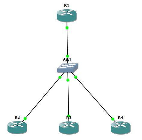
DMVPN Phase-1: Static Mapping
Let’s start by configuring R1 starting from GRE config, then NHRP:
interface Tunnel0
 ip address 10.1.1.1 255.255.255.0
 tunnel source FastEthernet0/0
 tunnel mode gre multipoint

 ip nhrp network-id 111
 ip nhrp map 10.1.1.2 192.168.1.2
 ip nhrp map 10.1.1.3 192.168.1.3
 ip nhrp map 10.1.1.4 192.168.1.4
GRE and NHRP config for R2:
interface Tunnel0
 ip address 10.1.1.2 255.255.255.0
 tunnel source 192.168.1.2
 tunnel destination 192.168.1.1

 ip nhrp network-id 111
As shown above in the GRE part for both routers, we needed to specify the tunnel source (you can do this by exit interface or IP address). The tunnel destination command differs between the Hub and the Spokes, since the spokes only need to form tunnels with the Hub here, they only need to pint to the public IP address of the Hub. However, the Hub will need multiple tunnels hence the multi-point command. ip nhrp network-id command activates NHRP on the tunnel. ID can be any value. NHRP map command is configured on the Hub only since the spokes will not need to map to different destination. Remember to use the tunnel/private IP then the public/physical-interface IP address.
Let’s continue with configuring R3 and R4
R3:
interface Tunnel0
 ip address 10.1.1.3 255.255.255.0
 tunnel source f0/0
 tunnel destination 192.168.1.1
 ip nhrp network-id 3
R4: interface Tunnel0 ip address 10.1.1.4 255.255.255.0 tunnel source 192.168.1.4 tunnel destination 192.168.1.1 ip nhrp network-id 444
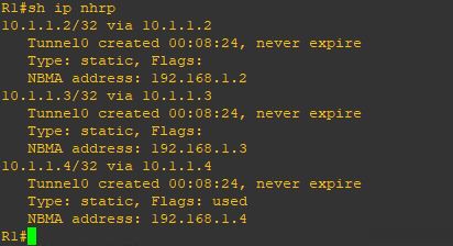
Let’s confirm that R1 is seeing all tunnels and have connectivity. Notice the ‘S’ flag for Static.

Let’s test site to site connectivity between the Hub and Spokes and between Spokes and Spokes:
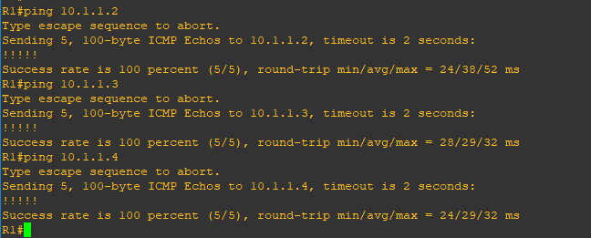
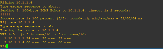
As you can see, we have full connectivity. Also as expected, each spoke will need to go through the hub to reach another spoke. Let’s try to run EIGRP across the DMVPN cloud:
On R1,2,3 and 4:
router eigrp 100
 network 10.1.1.0 0.0.0.255
At first, you will notice that on R1, all three adjacencies come up, however, none comes up on the spoke routers. If you wait enough time, you will see all adjacencies come down, and up again. Obviously, something is not right here.The issue is here is with Multicast. Point-to-point links do support Multicast. But point-multipoint links do not. Routers running EIGRP use multicast address 224.0.0.10 to communicate among eachothers Since, we are discussing static mapping, let’s add these commands on R1 and see if this does the trick:
R1:
interface Tunnel0
 ip nhrp map multicast 192.168.1.2
 ip nhrp map multicast 192.168.1.3
 ip nhrp map multicast 192.168.1.4
Now all adjacencies are stable once we fixed the multicast issue. Let’s check the routing table of the routers

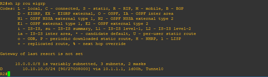
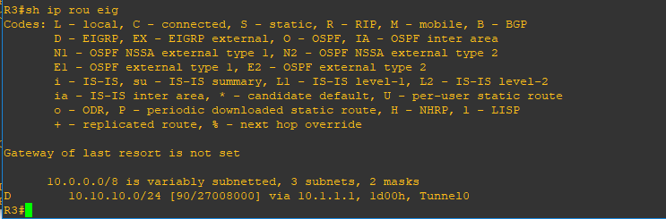
R1 has learned all routes, but R2, R3 and R4 (not shown yet) are not learning from each other. The reason behind that is EIGRP split-horizon. To fix this, we need to add the following:
R1
interface Tunnel0
 no ip split-horizon eigrp 100
Let’s check R4 routing table now
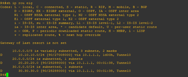
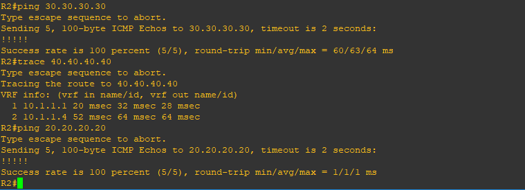
Now we should have full spoke to spoke connectivity
DMVPN Phase-1: Dynamic Mapping
To change the static mapping that we have configured to dynamic mapping, we need to do the following:
R1
interface Tunnel0
no ip nhrp map 10.1.1.2 192.168.1.2
no ip nhrp map 10.1.1.3 192.168.1.3
no ip nhrp map 10.1.1.4 192.168.1.4
no ip nhrp map multicast 192.168.1.2
no ip nhrp map multicast 192.168.1.3
no ip nhrp map multicast 192.168.1.4
ip nhrp map multicast dynamic
And for R1, R2 and R3, we add the following line:
interface Tunnel0
 ip nhrp nhs 10.1.1.1
As you notice, for R1 we removed all static mapping commands for and we replaced that with a single command. Also on the spoke sites, we used Next Hop Server command to instruct the spokes to go and register with R1, the Hub, which will maintain a list of all mappings (dynamic mapping in the case). Notice the ‘D’ flag for Dynamic below.
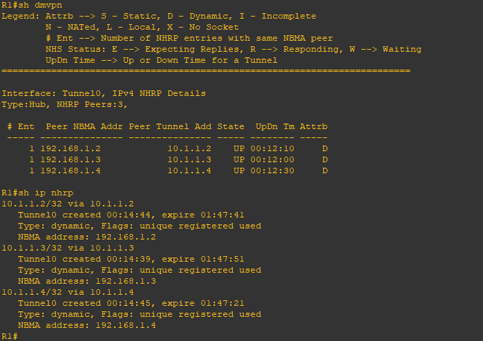
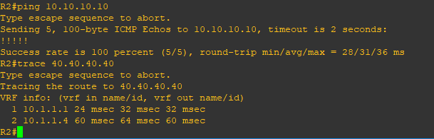
Let’s confirm connectivity again
In the next post, I will discuss DMVPN Phase 2
Enter the text or HTML code here
