As I mentioned in the previous L3VPN posts, those were using one specific architecture to connect two ISPs to each other, which is called Back to Back VRFs where a VRF is needed for each customer in both ISPs networks. Of course this is one way of making this to work. Another design is called carrier supporting carrier which I’m going to explain in this post.
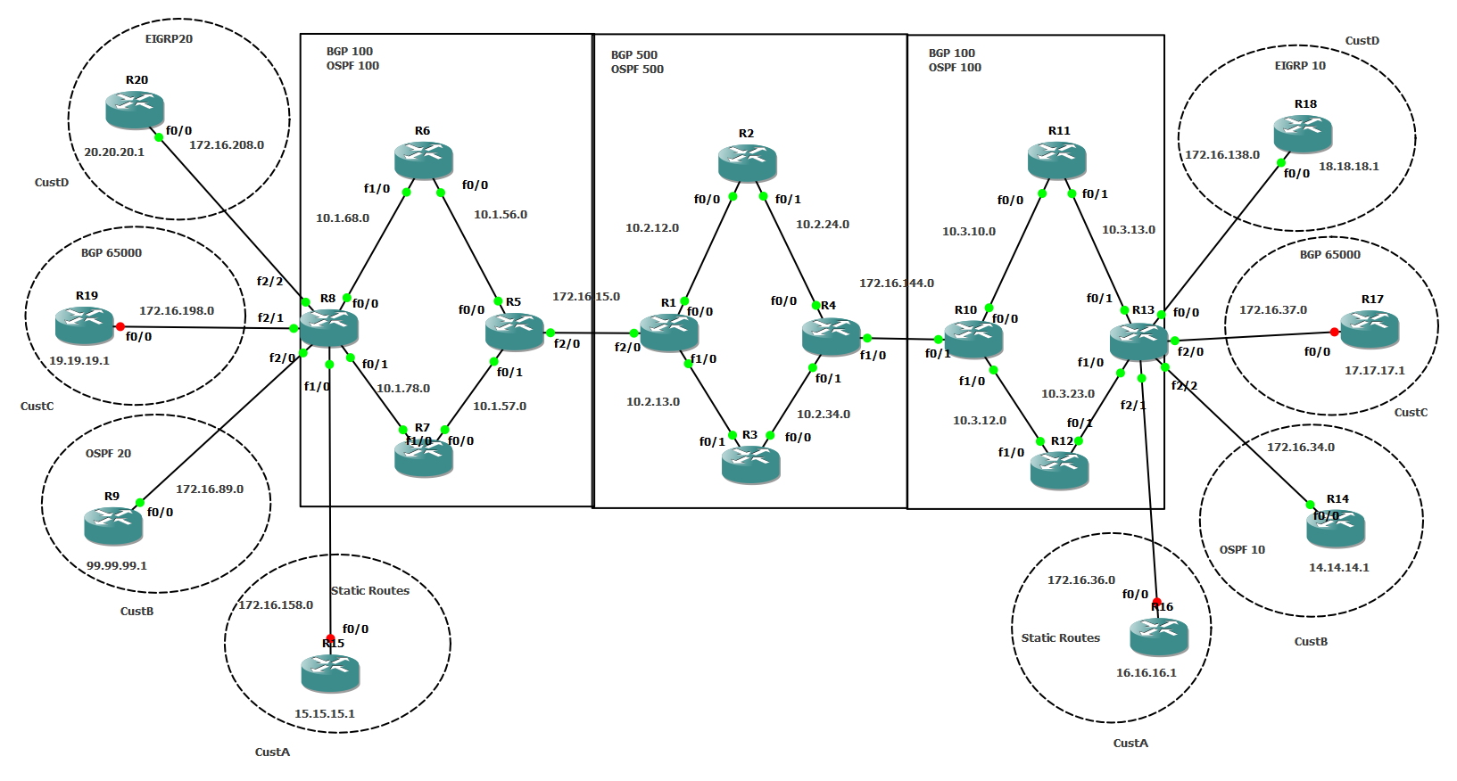
I’m going to use the same previous design with some slight changes, HERE is the complete diagram.
There are no changes in the customer sites configuration and they are exactly as I left them in the previous MPLS VPN series, so I am not going to copy their configuration here. All the configuration changes happen in both ISPs backbone, the PEs to be specific.
The terminology is also different here. PEs (R8 and R13) are still the PEs in ISP 100 that are facing the customers. CSC-CEs (R5 and R10) are now treated as Carrier Supporting Carrier – Customer Edges in ISP100 facing ISP 500’s (R1 and R4) which are called CSC-PEs.
First, I’m going to configure the same VRFs on both R13 and R8:
ip vrf CUSTA111
rd 111:11
route-target export 111:11
route-target import 111:11
!
ip vrf CUSTB222
rd 222:22
route-target export 222:22
route-target import 222:22
!
ip vrf CUSTC222
rd 333:33
route-target export 333:33
route-target import 333:33
!
ip vrf CUSTD222
rd 444:44
route-target export 444:44
route-target import 444:44
!
No VRFs are needed on R10 or R5 and this is one of the big differences from the Back to Back VRFs. Also, I’m not going to iBGP peer R13 with R10 or R8 with R5, another big difference. I am going, however,to iBGP peer R8 all the way with R13 using ISP 500 backbone. And this is the idea of the CSC architecture.
In order to do this, I will need to eBGP peer R10 with R4 and R5 with R1. VERY important is to exchange the MPLS labels between both ISPs. To do that, I can either use IGP with LDP or BGP without LDP. The preferred method is to use eBGP to transfer the MPLS labels as shown below.
R10:
interface FastEthernet0/1
ip address 172.16.144.2 255.255.255.0
speed 100
full-duplex
!
router bgp 100
bgp router-id 10.10.10.10
no bgp default route-target filter
bgp log-neighbor-changes
neighbor 172.16.144.1 remote-as 500
!
address-family ipv4
neighbor 172.16.144.1 activate
neighbor 172.16.144.1 allowas-in
neighbor 172.16.144.1 soft-reconfiguration inbound
neighbor 172.16.144.1 send-label
no auto-summary
no synchronization
network 13.13.13.13 mask 255.255.255.255
exit-address-family
!
R5:
interface FastEthernet2/0
ip address 172.16.15.2 255.255.255.0
speed 100
full-duplex
!
router bgp 100
bgp router-id 5.5.5.5
no bgp default route-target filter
bgp log-neighbor-changes
neighbor 172.16.15.1 remote-as 500
!
address-family ipv4
neighbor 172.16.15.1 activate
neighbor 172.16.15.1 allowas-in
neighbor 172.16.15.1 send-label
no auto-summary
no synchronization
network 8.8.8.8 mask 255.255.255.255
exit-address-family
!
As noticed above, pretty much straight forward eBGP configuration. The command neighbor x.x.x.x send-label is where eBGP exchanges MPLS labels.
Proceeding with R1 and R4 on the other side of this eBGP peerings:
R4:
ip vrf CsC-ISP500
rd 4.4.4.4:500
route-target export 500:100
route-target import 500:100
!
interface FastEthernet1/0
ip vrf forwarding CsC-ISP500
ip address 172.16.144.1 255.255.255.0
speed 100
full-duplex
!
router bgp 500
no synchronization
bgp router-id 4.4.4.4
bgp log-neighbor-changes
neighbor 1.1.1.1 remote-as 500
neighbor 1.1.1.1 update-source Loopback4
no auto-summary
!
address-family vpnv4
neighbor 1.1.1.1 activate
neighbor 1.1.1.1 send-community both
exit-address-family
!
address-family ipv4 vrf CsC-ISP500
neighbor 172.16.144.2 remote-as 100
neighbor 172.16.144.2 activate
neighbor 172.16.144.2 send-label
no synchronization
exit-address-family
!
R1:
ip vrf CsC-ISP500
rd 4.4.4.4:500
route-target export 500:100
route-target import 500:100
!
interface FastEthernet2/0
ip vrf forwarding CsC-ISP500
ip address 172.16.15.1 255.255.255.0
speed 100
full-duplex
!
router bgp 500
no synchronization
bgp router-id 1.1.1.1
no bgp default route-target filter
bgp log-neighbor-changes
neighbor 4.4.4.4 remote-as 500
neighbor 4.4.4.4 update-source Loopback1
no auto-summary
!
address-family vpnv4
neighbor 4.4.4.4 activate
neighbor 4.4.4.4 send-community both
exit-address-family
!
address-family ipv4 vrf CsC-ISP500
neighbor 172.16.15.2 remote-as 100
neighbor 172.16.15.2 activate
neighbor 172.16.15.2 next-hop-self
neighbor 172.16.15.2 send-label
no synchronization
exit-address-family
!
One last step, for now, is to inject BGP learned routes into OSPF on both CSC-CEs (R5 and R10):
router ospf 100
redistribute bgp 100 subnets
A couple of things to explain before moving forward:
– ISP500 needs one VRF (CsC-ISP500) for ISP100 AND all its customers. ISP500 simply has no visibility to any of ISP100 customers’ routes.
– I showed the MP-BGP peering between R1 and R4 again here even though it was already configured in the previous example but I wanted to emphasize that we are still peering MP-BGP between R1 and R4.
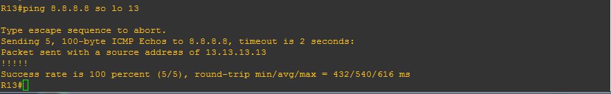
– Since the end goal is to peer between R8 and R13, I am advertising their loopback interfaces from ISP100’s CSC-CEs to ISP500’s CSC-PEs.
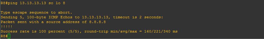
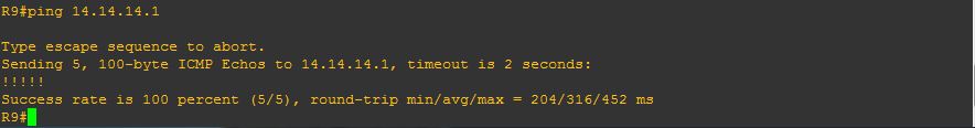
At this point, R8 and R13 should be able to ping each other:
Now that we have confirmed connectivity. Let’s configure MP-iBGP between R8 and R13:
R8:
router bgp 100
no synchronization
bgp router-id 8.8.8.8
bgp log-neighbor-changes
redistribute eigrp 10
neighbor 13.13.13.13 remote-as 100
neighbor 13.13.13.13 update-source Loopback8
no auto-summary
!
address-family vpnv4
neighbor 13.13.13.13 activate
neighbor 13.13.13.13 send-community both
exit-address-family
!
R13:
router bgp 100
no synchronization
bgp router-id 13.13.13.13
bgp log-neighbor-changes
neighbor 8.8.8.8 remote-as 100
neighbor 8.8.8.8 update-source Loopback13
no auto-summary
!
address-family vpnv4
neighbor 8.8.8.8 activate
neighbor 8.8.8.8 send-community both
exit-address-family
!
Now let’s verify that BGP is up between them:
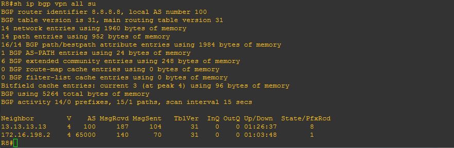
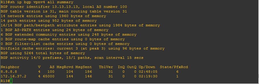
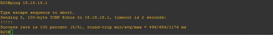
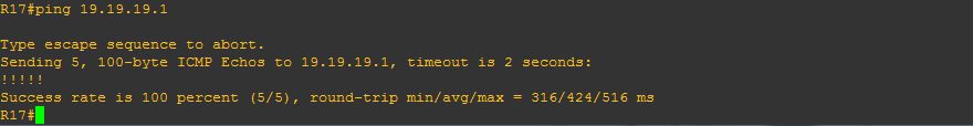
All configuration is complete now. We should have customer connectivity across both ISPs, let’s confirm that:
Enter the text or HTML code here
